Sigalon Security Systems AB
Monitoring and Control System for Emergency Smoke Evacuation and Comfort Ventilation
Background
According to laws and regulations, every building (family homes are excluded) has to be equipped with facilities for detection and evacuation of fire and smoke gases.
Typically, today, a smoke evacuation system consists of roof and/or front mounted ventilators with one or two motor driven shutters.
Many older systems are using electro-magnets to keep the ventilator closed and when the electricity is cut off, the ventilator opens. In order to restore operation, these ventilators have to be closed manually – many times a very dangerous and difficult undertaking.
These systems are installed with conventional control systems. Such systems are often characterized by high installation cost, low operating flexibility and very limited, if any, control, management and reporting facilities.
Recent changes of laws and regulations increase the responsibilities of property owners. New systems and reporting procedures are required in order to further protect against accidents.
Opportunity
In order to meet current and future requirements, Sigalon Security Systems has recognized the drawbacks with the currently available systems and decided to develop and market a new cost effective and flexible Monitoring and Control System for Emergency Smoke Evacuation and Comfort Ventilation.
System overview
This new system from Sigalon Security Systems has the following main characteristics:
1. The roof and/or front mounted motor driven ventilators are guided by signals obtained from connected sensors, computer based controls and manual interventions.
2. In a previous version of the system, all electrical power required by the different system components, as well as the data communication between the different components, were provided by only one fireproof electrical cable.
3. Currently, the system is a self contained, light (solar) energy based system, fully independent from any central electrical power.
4. For a ventilator, the system provides Master and Slave functions (see below) and support for two electrical spindle motors, sensor entries, light (solar) panel, charger, battery, radio and antenna.
5. New ventilators might have all the required components preinstalled.
6. The costly, and sometimes complicated, electrical installation is totally avoided. Compared to a conventional installation, the new system provides a significant reduction in total costs.
7. All communication between different components of the system; PC, Masters, Slaves, sensors, manual interventions, motors and shutters etc. is wireless, provided by radio based signals.
8. The communication system provides full flexibility as all components, with corresponding event and action variables, maximum/minimum limit values and their interrelated priority order, are very easy to define and modify by authorized system users.
9. The system checks, with user specified frequency, that all components in the system are functional.
10. All events and related actions, automatic as well as manual, are automatically logged on a PC.
11. The system can be compared to a separate data network, each component can be viewed as a terminal, each one with it’s unique address.
12. In the unlikely case of total unavailability of electrical power, the motor driven shutters can be opened/closed, using an external portable battery driven power interface.
13. The PC can be connected to an internal local area network and/or internet and mobile networks for sending and/or receiving information.
14. The system might be integrated with, and receive information from, a centralized security system, and execute required actions from such system.
15. Event/action and component status reporting is provided according to company and external authority requirements.
16. The cost effective, Monitoring and Control System for Emergency Smoke Evacuation and Comfort Ventilation from Sigalon Security Systems provides full flexibility when it comes to security, functional readiness, handling and reporting.
Description of system functions and components
Emergency Smoke Evacuation
1. Based on the signals from the attached Slave unit, the shutters of the ventilator will open and close.
2. Each movement of a shutter, and the reason, is automatically logged.
3. The open/closed status of the ventilator is automatically controlled and logged.
4. The proper operational function of the ventilator is controlled and logged according to required frequency.
5. Each shutter is opened and closed individually, based on user defined parameters and priorities.
6. Each shutter can be opened and closed on a direct command from the PC.
7. Each ventilator can be opened and closed, using a manually operated Control Box.
8. Each shutter can be opened/closed, using a potable external battery driven power interface.
Comfort Ventilation
1. If required, a ventilator might be used for comfort ventilation.
2. Each shutter can be opened and closed based on the parameters and priorities provided by the authorized system user.
3. Each shutter can be opened and closed on a direct command from the PC.
4. Each shutter can be opened and closed, using a manually operated control box.
5. Therefore, each shutter may, for example, be automatically opened/closed based on specified temperatures and/or fully manually and, in addition, automatically closed in the event of rain.
6. Comfort ventilation might provide for a better working environment and might lead to, sometimes considerable, cost reductions for e.g. air conditioning.
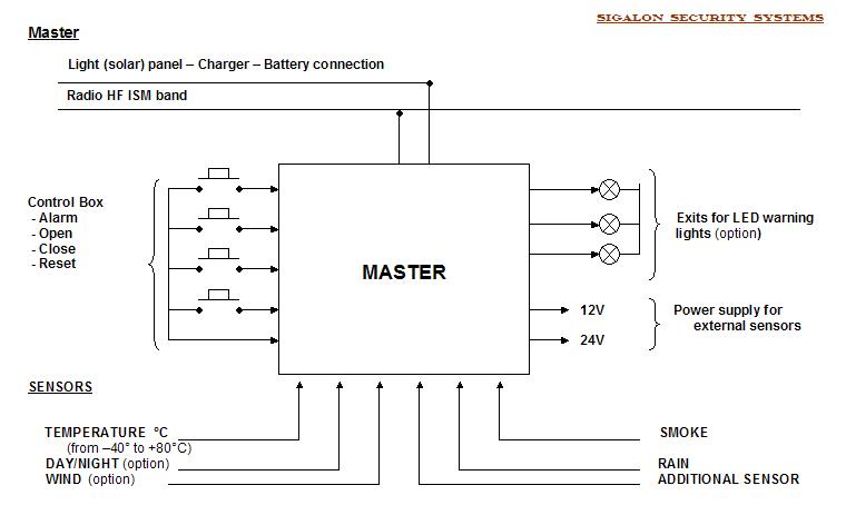
Master
1. Receives event signals from attached sensors, e.g. smoke, temperature, rain, wind and day/night.
2. Transmits action signals to attached Slave units.
3. Controls electrical power (12V or 24V) to attached sensors.
4. Provides exits for LED warning lights.
5. Communicates with the Manual Control Box for direct operation (opening/closing) of vents via attached Slave units.
6. Has exits for additional functions; e.g. a sound warning signal.
7. Controls regularly that attached Slaves units are in working order.
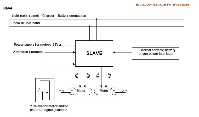
Slave
1. Controls two motors; one ventilator with two motor driven shutters or two ventilators with one motor each (e.g. front mounted ventilators).
2. Controls electrical power (24V) to connected motors.
3. Receives action signals from Master and/or PC and executes the required action.
4. Has contacts that regularly control and signal if a shutter is opened or closed.
5. Motor driven shutters might be opened/closed automatically or manually for comfort ventilation.
6. Has a security breaker that automatically stops the movement of a motor driven shutter, should an object obstruct the open/close movement.
PC Interface
1. Is used as a radio based communication interface between the system components – Masters and Slaves – and a standard PC.
Standard PC
1. The system uses a standard PC (with a UPS) running Microsoft Windows (currently version XP).
2. The PC is used, via the Interface, to initiate fixed and variable system parameters incl. the assigning of unique addresses to systems components.
3. Some of these parameter values are downloaded to, and stored in, micro processors in the Master and Slave units.
4. Using a simple user interface; system components, parameter values and current status are easily supervised.
5. Authorized staff may easily modify system parameters, using eg. a touch screen interface.
6. All events and related actions; automatic as well as manual, are automatically and regularly logged, incl. date, time, event, action, status, component ID and, if a manual intervention, the ID of the individual initiating the action.
7. The system might easily be connected to a company local area network and/or the Internet and delivers required information according to specified rules.
8. The system might be integrated with, and receive information from, a centralized security system, and execute required actions from such system.
9. System parameters and variables might be modified of staff with proper security and access rights.
10. The system might be connected to Internet and mobile networks.
11. As required, the system delivers warning, ad hoc and regular reports to internal and external information users.
12. The PC might be equipped with a Remote Control program. This will facilitate e.g. systems maintenance and upgrades from an authorized PC via the Internet or a direct modem connection.
13. As the system is operating on a continous basis, a PC WatchDog program might be used. This will ensure an around the clock monitoring of the PC. If a problem occurs, the system will automatically restart the application and/or provide an appropriate signal to the person responsible for the system.
Benefits
-
Maximum use of radio based wireless communication technology.
-
Maximum use of free and environment friendly energy sources; solar and other light sensitive panels.
-
Very low energy consumption.
-
No expensive electrical installation.
-
No specialist training of personnel.
-
One supplier of system hardware and software;
- Sigalon Security Systems.
-
System installation by professionals, trained and certified by;
- Sigalon Security Systems
-
One provider of systems maintenance and upgrades;
- Sigalon Security Systems.